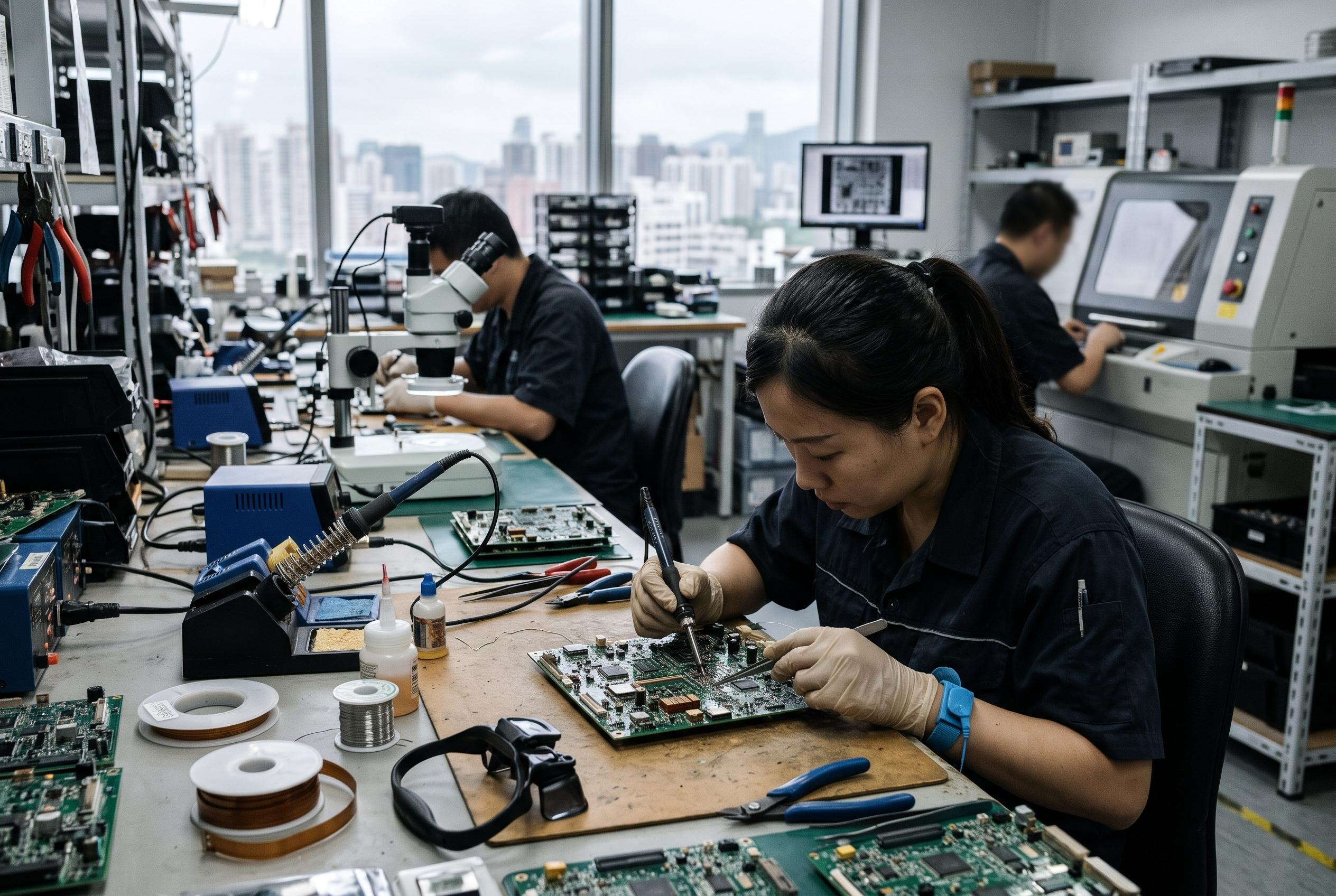
Designers are increasingly soldering circuit boards directly together to save space, reduce connector count, and create compact electronics. The approach works well when footprints, plating, heat access, and mechanical support are planned together, but a quick solder job won't rescue mismatched edges or fragile layouts.
Direct board-to-board soldering saves space, but demands planning
PCB-to-PCB soldering can create a neat, low-profile connection, especially when a small module sits on a carrier board. Castellated modules, soldered pins, designed edge joints, and supported flex terminations are all viable options when the mating features are purpose-built.
The key distinction is simple: exposed, solderable copper must meet a matching feature. Two ordinary board edges coated in solder mask won't magically become a dependable electrical joint. According to BestPCBs, the design must also account for inspection access and the mechanical path through the finished assembly.
Direct soldering can reduce component count and connector height, which is appealing in compact products. But it also makes servicing harder. If a board may need regular removal, a separable board-to-board connector could be the less glamorous but more sensible choice.
Castellated modules remain the popular compact option
Castellated holes are plated holes cut through a module's edge, leaving curved copper surfaces that can be soldered to matching carrier-board lands. The outside fillet is visible, making inspection easier than with a completely hidden joint, although it still won't reveal every interface underneath the module.
Alignment matters down to the details. Designers should compare pin-one orientation, pitch, row spacing, land size, board thickness, underside clearances, and any antenna or keepout zones. A footprint that looks perfect from above may still clash with a bottom-side component or place copper in a sensitive area.
A dry fit is a worthwhile habit before soldering prototypes. If one end lines up while the other drifts, don't use solder as a brute-force alignment tool. That can leave the module under stress, and the problem may only appear after cooling or during later testing.
Flex-to-rigid soldering needs strain relief
A flexible PCB can be soldered to a rigid board, but only at a designed termination. The flexible dielectric itself isn't solderable, so the exposed fingers, coverlay opening, surface finish, and nearby support all need to suit the chosen process.
Keep the bend zone away from the soldered transition. Solder that wicks into the flex can stiffen a small area and concentrate bending stress at the end of the joint. As guidance from PCBSync and FlexPCB.org notes, a stiffener or fixture can help hold the termination steady, while separate strain relief protects it during use.
This is where a connector or rigid-flex construction may earn its keep. A soldered flex joint can be wonderfully slim, but it isn't automatically the best answer for a cable that must be replaced, repeatedly moved, or exposed to vibration.
Hand soldering works when access and heat are controlled
For prototypes and accessible castellated connections, hand soldering can be practical. Use a stable holder, magnification, suitable fume extraction, and an ESD-conscious setup. The usual sequence is to tack one corner, check seating and orientation, secure the opposite side, then complete the remaining joints with controlled solder volume.
The iron tip needs to heat both the carrier land and the module's plated edge. A tiny tip with poor thermal transfer can struggle against a large ground connection, while an oversized tip can flood neighbouring pads. Use electronics solder with an appropriate alloy, flux core, and wire diameter. Plumbing flux doesn't belong on a circuit board.
Don't chase a difficult joint simply by increasing the iron temperature. Tip condition, contact area, flux activity, copper mass, and heating time may be the real issue. Soldering-temperature guidance from BestPCBs stresses that an iron's displayed setpoint doesn't equal the actual joint temperature.
Reflow brings repeatability, but not automatic reliability
Reflow is useful when the module, carrier, paste, stencil, and surrounding components are all qualified for the thermal process. It can join many contacts consistently, but the oven won't correct a misplaced footprint or uneven paste deposit.
Stencil aperture design and thickness influence solder volume, bridging, and how flat the module sits. Inspect the print and placement before heating, then measure the loaded assembly rather than relying on a machine's nominal settings. The correct profile depends on the paste alloy, module limits, laminate, component mix, and previous thermal exposure.
Flexible boards add another layer of caution. PCBMaster's SMT guidance highlights the importance of support and process control when working with flexible materials, which can shift or distort during assembly. In production, the best process is the one that gives operators repeatable alignment, inspectable joints, and a clear route for rework.
Mechanical support protects the electrical connection
A small daughterboard can act like a lever. Cable pull, connector insertion, vibration, enclosure flex, and thermal expansion can all load solder joints that were never meant to carry the assembly's mechanical burden.
Use standoffs, approved mounting features, retention hardware, or another suitable support arrangement where needed. Keep those supports clear of live conductors, antennas, and components. The goal is to route forces into the enclosure or carrier structure instead of concentrating them at the board edge.
Inspection should cover more than appearance. Check seating, bridging, wetting, plating damage, unintended shorts, and electrical function. Continuity is useful, but a meter beep doesn't prove that a joint will survive vibration or temperature cycling. As Well Circuits explains, the connection needs both electrical and mechanical validation.
A direct solder joint can be elegant, compact, and dependable, but only when the layout and load path are designed as one system.
Choose the connection style that fits both your circuit and its real-world service demands.
Disclaimer: This article may have been created with AI assistance and reviewed by our editorial team. It is provided for general informational purposes only. Readers should verify information independently before relying on this content.